- Homem
- Advance 8051 Microcontroller Trainer Kit
Advance 8051 Microcontroller Trainer Kit
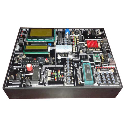
Advance 8051 Microcontroller Trainer Kit
SPECIFICATIONS
- CPU: Philips 89V51RD2 Microcontroller with clock frequency@11.0592MHz.
- Four Seven Segment Displays
- 16x2 LCD Display Interface
- Graphical LCD Interface
- EWSN Status LED’s 8 Nos.
- 8 Channel ADC Interface
- DAC 0800 Interface
- LED Matrix Interface
- 4x4 Matrix Keyboard Interface
- PS2 Keyboard Interface
- Traffic Light Interface
- Stepper Motor Controller interface with stepper motor
- Buzzer Interface
- PWM & Interrupt Interface
- Eight Data Switches
- LM35 Temperature Interface
- IR Interface
- Relay
- Opto
- Real Time Clock with battery backup
- At24C16 Serial EEPROM
- USB Interface
- RS-485 Interface
- RS-232 Interface using Rx/Tx of MCU for uploading/downloading
- On-chip Flash Program Memory with ISP and IAP capability
- ADC,DAC interfacing card Elevator Interfacing Card
- Temperature loop interface card

Tell us what are you "Looking for?"
Related Product
Related Product
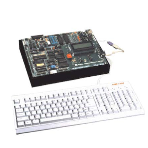
8085 Microprocessor Kit
8085 Microprocessor Kit with Accessories/Peripherals and Interfacing Devices. SPECIFICATIONS In addition to normal specifications. 8251 study card USART 8279 study card 8255 study card. SRAM and DRAM interface card with converter card DMA Controller. Battery Backup for RAM. Total on-Board memory expansion to 384 KB. 72 programmable I/O lines through 8255. Real time Clock interfaces. Three 16-bit Timer/Counter through 8253. RS 232C serial interface through 8251. USB Interface for PC Interface 8 different level of interrupt through 8259. 1 Mask able interrupts. 8 non-maskable interrupt On-board A/D Converter On-board D/A Converter On-board Relay having 2 NO and NC contacts. On-board Opto Isolated input On-board 8 Digital inputs On-board 8 Digital Outputs On-board Temperature Sensor On-board Traffic light controller On-board Printer Interface 20*2 LCD Display (40x2 optional) 104 Keys IBM Compatible Key Board (USB) Two modes of Commands key board mode and serial mode. All address data and control lines available at FRC connector as per multi-Bus. Facility for Down/Up loading files from/to PC With Built in Power Supply
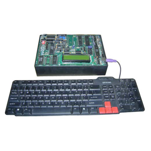
Microcontroller Development Board
SPECIFICATIONS Microcontroller: 8031/8051/8751/89C51compatible Main RAM: 32KB(62256) Monitor ROM: 32KB(27256) Display Unit: LCD(16x2 Line) I/O Port: CPU I/O Port, 8255Ax 2 Dot Matrix LED: 8x8 Keyboard: 16 keys for data, 8 keys for function Integration and Development Environment Program Display 8051 internal architecture or Equivalent Source code editing, assembling, compiling and program writing Code memory disassemble 8051 Register, internal/external memory dump and editing function Source level debugging function Pop-up menu and 89C51 WRITE function A/D, D/A Converter facility D.C. Motor and Photo Interrupter sensor Speaker and Step Motor Interface Circuit Expansion Connector System bus Minimum 40 pins text tool Power sce: 220V AC ±10%, 50 Hz Accessories: Software CD, PC interface cable and Instruction Manual
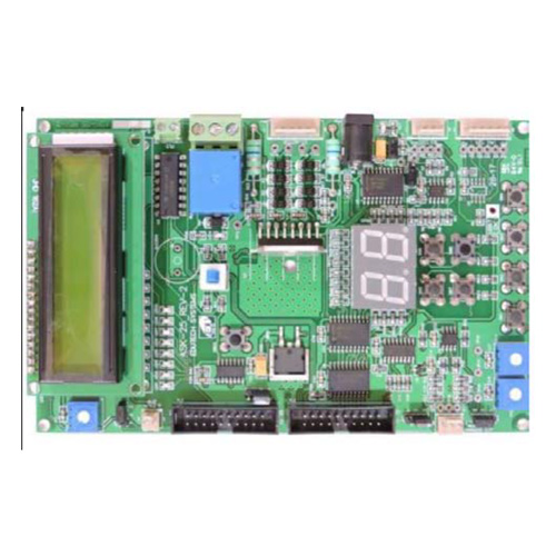
All-in-One General Purpose Board
SPECIFICATIONS The All-in-one GPIO board is specially designed to suit the experimentation of different GPIO devices with the microcontrollers. It includes 8 LED. 16x2 character LCD. 2 digit 7-segment display. Switches includes 4 general purpose keys. 2x2 matrix keyboard. I2C based EEPROMs for protocol demonstration experiments. SPI based EEPROMs for protocol demonstration experiments. Stepper motor interface facility. DC Motor interface. Relay output. Facility to provide 2 channel ADC input using potentiometer and unity gain amplifier for protection. Useful resource to learn basic programming techniques to interface basic GPIO components to the controller. GSM Modem with enclosure: GSM modem with serial communication interface. Standard RS-232 interface using DB9 connector provided for communication. Controlling through AT commands. Modem can be linked to a PC, micro-controller or DSP based embedded system for sending SMS. Data circuit asynchronous, transparent and non-transparent up to 14400 bits/s and baud rate of 30 to 115,200 bits/s. Metal enclosure case. Power supply – 12V SMPS power supply. SIM800 modem. Can be used for curriculum projects involving Pre-stored messaging, Remote home appliance control, Industrial alarming system, Automatic Meter Reading (AMR), Security Systems, Remote Data logging and reporting, Low cost router, Remote monitoring of Vending machines etc. Finger print module with enclosure: Image acquiring time - <0.5s. Storage capacity – 256. FAR - <0.001%. Average searching time - <1s. Working environment – (-10 to 40) Degree C. Working current – 100mA peak. Matching mode - 1:1 and 1:N. Character file size – 256. Interface – UART. Template size – 512 bytes. Power supply through 2 pin relimate connector. UART Relimate Connector to TTL signal. Power Supply Connector. USB B-B Power Supply Connector. U..
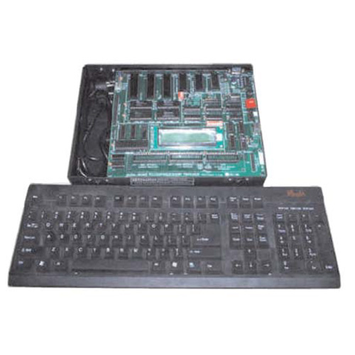
8086 Microprocessor Kit
8086 Microprocessor Kit With Accessories/Peripherals SPECIFICATIONS Compatible with 8088 Microprocessor (8 bit). Provision to add 8087 Co- processor & 8089 I/O Processor. 256 KB of CMOS RAM using 62256. 512 KB of EPROM loaded with monitor expandable further using 27512. Battery Backup for RAM. Total on-Board memory expansion to 384 KB. 72 programmable I/O lines through 8255. Real time Clock interfaces. Three 16-bit Timer/Counter through 8253. RS 232C serial interface through 8251. USB Interface for PC Interface. 8 different level of interrupt through 8259. 1 Mask able interrupts. 8 non-maskable interrupt. On-board A/D Converter. On-board D/A Converter. On-board Relay having 2 NO and NC contacts. On-board Opto Isolated input. On-board 8 Digital inputs. On-board 8 Digital Outputs. On-board Temperature Sensor. On-board Traffic light controller. On-board Printer Interface. 20*2 LCD Display (40x2 optional). 104 Keys IBM Compatible Key Board (USB). Two modes of Commands key board mode and serial mode. All address data and control lines available at FRC connector as per multi-Bus. Facility for Down/Up loading files from /to PC. With Built in Power Supply. 8251 study card USART 8279 study card 8255 study card. SRAM and DRAM interface card with converter card DMA Controller.
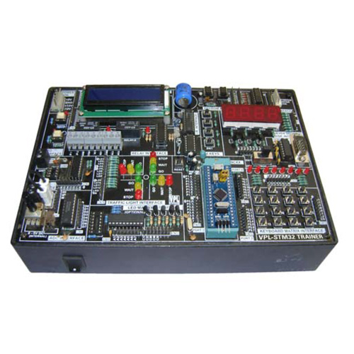
Embedded AI-Enabled Development Platform & Wireless Communication Modules
SPECIFICATIONS Processing Unit MCU: STM32N657X0. CPU: Dual-core Arm® Cortex®-M7 (480 MHz) + Cortex®-M4 (240 MHz). DSP & AI Acceleration: FPU (Floating Point Unit) for high-speed DSP computations. CMSIS-DSP and CMSIS-NN support for machine learning. TensorFlow Lite for Microcontrollers compatibility. Memory & Storage RAM: 1MB SRAM + 512KB TCM (Tightly Coupled Memory). Flash Storage: 2MB embedded Flash. External Storage: Micro SD card slot, QSPI NOR Flash (128MB). Connectivity Ethernet: 10/100 Mbps. Ethernet with hardware TCP/IP. Wi-Fi & Bluetooth: External module support via UART/SPI. USB Ports: 1x USB 2.0 OTG (Host/Device). 2x USB 2.0 Host Type-A. CAN Bus: 2x CAN FD for automotive/industrial applications. UART, I2C, SPI, GPIO: Multiple I/O interfaces. Display & Camera Interface Display Output: MIPI DSI for LCD (Optional Display Panel). Camera Interface: MIPI CSI-2 (Supports up to 2 cameras simultaneously). Expansion & I/O GPIO Header: 40-pin expansion connector (Raspberry Pi HAT compatible). STMod+ Connector: Supports additional sensor modules. PCIe Expansion: M.2 Key E for Wi-Fi/Bluetooth modules. Power Supply & Efficiency Input Power: 5V/3A via USB-C or external power supply. Low-power modes: Dynamic voltage scaling, deep sleep mode. Operating Environment Temperature Range: -40°C to +85°C (Industrial-grade). Cooling: Passive heat sink, supports active cooling fan. Operating System & Software Support OS Support: Bare Metal, FreeRTOS, Zephyr RTOS. DSP & Edge AI Support: TensorFlow Lite, CMSIS-DSP, CMSIS-NN. Programming Languages: C, C++, Python, MATLAB. Security Features: Secure boot, Trust Zone, AES encryption. Controller & Programming Environment Software Development Kit: STM32CubeMX, STM32Cube.AI, FreeRTOS, Zephyr. Programming Languages: C, C++, Python. Real-time Processin..


